
BPMN 2.0: A Practical Guide to the Notation
Learn how BPMN 2.0 represents processes, from events and activities to gateways, pools, lanes, and artifacts.

A practical guide to BPMN 2.0: the standard, its symbols, and how to use them
BPMN is a standard way to draw business processes so people can see what happens, who is involved, and how work moves from one step to the next. BPMN 2.0 defines the notation and a shared XML format, making it easier to discuss, document, and exchange process models.
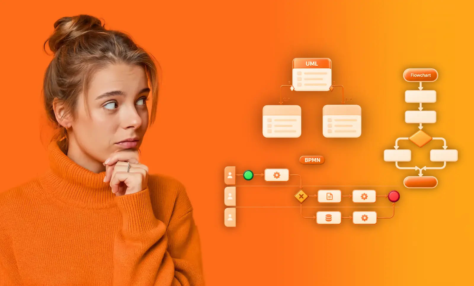
Use the navigation below to jump to the symbol family you need. You can also compare BPMN with other notations in our guide to BPMN, UML, and flowcharts.
You do not have to read this page first. Open the BPMN 2.0 modeler, describe a process you already know in a sentence, and let it draw the first draft; then use the reference below to correct that draft symbol by symbol. That is faster than learning the notation on its own, and you can start a model right now without installing anything.
Jump to the BPMN symbol reference
What is BPMN 2.0?
BPMN stands for Business Process Model and Notation. The Object Management Group (OMG) publishes and maintains the standard. It gives modelers a shared visual language for describing a process, from its start and end points to the tasks, decisions, and handoffs in between.
BPMN 2.0 was published in 2011. One important addition was XML serialization: a standard way to store a model so different tools can read and exchange it. The notation is vendor-neutral, so the symbols do not belong to a particular modeling tool. That is what made it the business process management notation that organizations and vendors settled on, instead of one more house style.
A BPMN diagram can help you explain a process to colleagues, document how work is intended to happen, or create a model precise enough for a workflow engine. The level of detail depends on your purpose. A communication model does not need to specify every technical implementation detail.
Why use BPMN 2.0?
BPMN gives business and technical teams a common way to discuss process steps and responsibilities. Its symbols have defined meanings, so readers do not have to learn a new legend for every diagram, and a BPMN process can leave the tool it was drawn in.
A BPMN model can help you:
- Explain how work flows. Show the order of activities, decision points, and outcomes in one diagram.
- Clarify responsibilities. Use pools and lanes to show which participants and roles are involved.
- Document exceptions. Model alternate paths, events, and different end states alongside the main flow.
- Exchange models. Use BPMN 2.0 XML to move a model between tools, while checking whether tool-specific details also transfer.
- Review and improve a process. Compare the documented model with how work actually happens. Process mining can add evidence from event data; it does not change the process by itself.
If you are choosing a tool, see our overview of BPMN tools. ProcessMind also brings process modeling and process mining together, so you can connect a documented process to operational data.
We work with BPMN 2.0 and value stream mapping because they are the standards everybody already uses. Are they perfect? No. They are good enough, and being the language your partners, auditors and other tools already read is worth more than the few improvements we could invent on our own. A shared notation is what lets two teams improve the same process together.
BPMN 2.0 elements at a glance
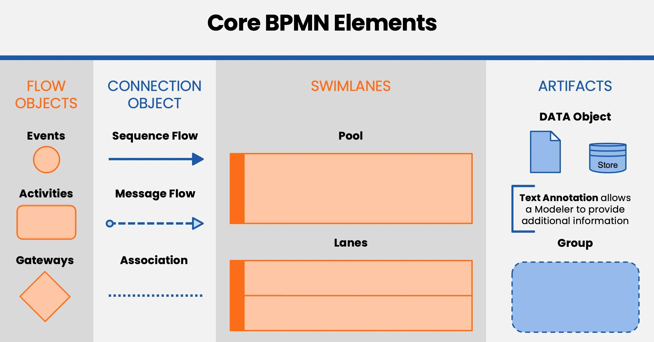
BPMN groups its elements into four families. The table gives you a quick reference; jump to a section for details.
| Family | Elements | What they show |
|---|---|---|
| Flow objects | Events, activities, gateways | What happens, what work is done, and where the flow branches |
| Connecting objects | Sequence Flow, Message Flow, Association | How elements connect and how work or information moves |
| Swimlanes | Pools and lanes | Which participants and roles are involved |
| Artifacts | Data Objects, Data Stores, Groups, Text Annotations | Information and context that help explain the process |
For a complete element list, see the BPMN building-blocks reference and the BPMN element icon guide. You can also download the BPMN 2.0 poster in your language.
Events
Events represent something that happens during a process. They appear as circles, with different borders to show where they occur:
- A Start Event has a thin border.
- An Intermediate Event has a double border.
- An End Event has a thick border.

Start Event
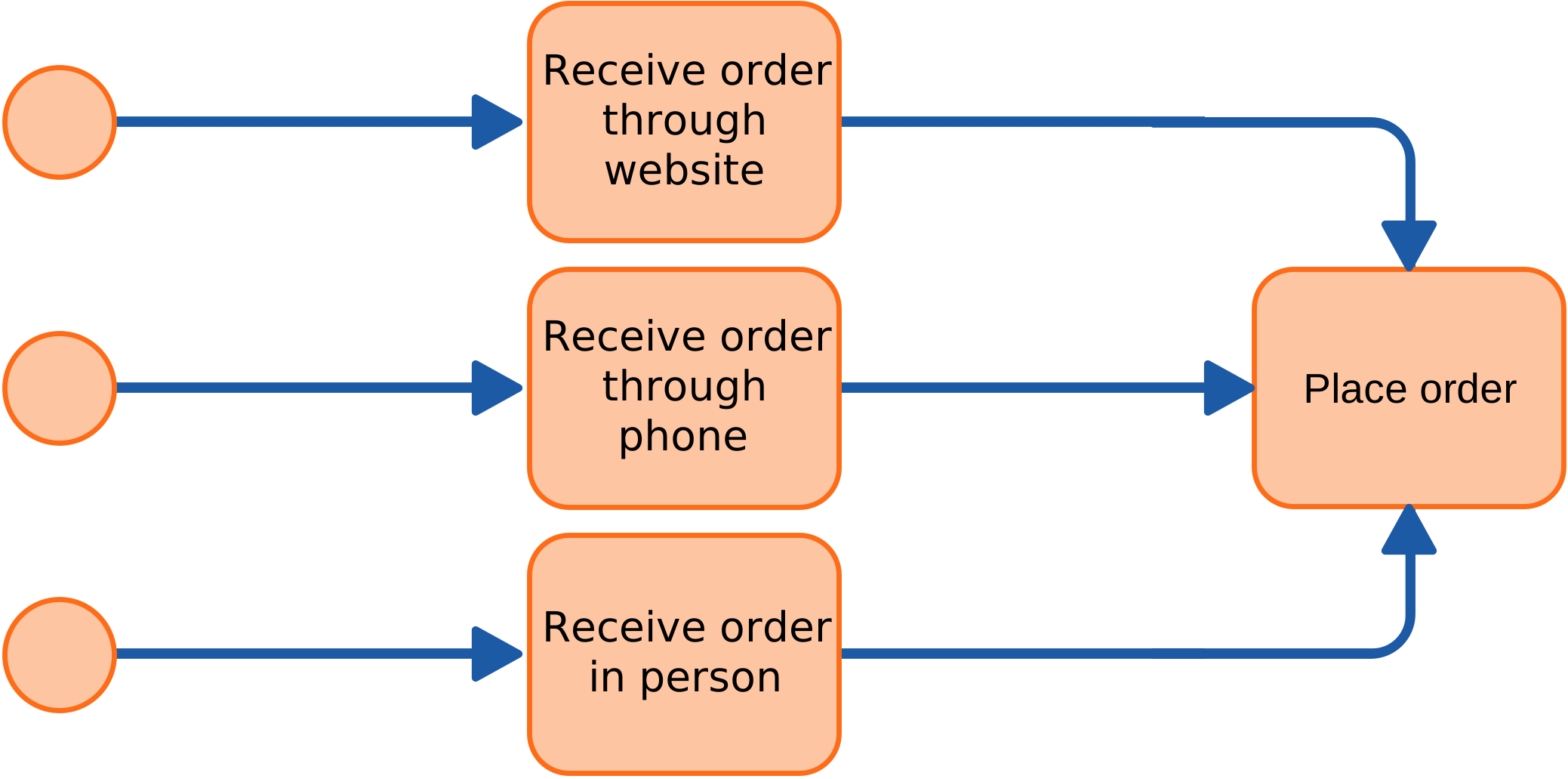
A Start Event marks where a process or path begins. A process can have more than one Start Event when different triggers can initiate it. For example, an order process might start when a customer places an order online, by phone, or in person.
Intermediate Event
An Intermediate Event occurs between the start and end of a process. Depending on its type and position, it can catch or throw an event, such as a message or signal. Other event types include Timer, Error, Escalation, Compensation, Conditional, Cancel, Link, Terminate, Multiple, and Parallel Multiple.

For example, an order process might wait for a customer confirmation message before continuing. The event symbol shows what the process is waiting for or sending.
End Event
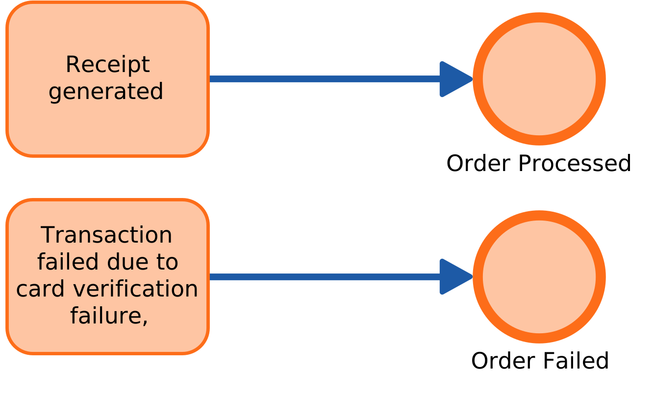
An End Event marks the end of a process path. A process can have multiple End Events to show different outcomes, such as an order being completed or rejected. Give each outcome a clear name so readers can distinguish them.
Event symbols
| Start | Intermediate | End | ||||||
|---|---|---|---|---|---|---|---|---|
| Type | Normal | Event Sub process | Event Sub process non-interrupt | Catch | Boundary | Boundary non-interrupt | Throw | |
| None | | |||||||
| Message | | | | | | | | |
| Timer | | | | | | | ||
| Conditional | | | | | | | ||
| Link | | | | |||||
| Signal | | | | | | | | |
| Error | | | | |||||
| Escalation | | | | | | | ||
| Termination | | |||||||
| Compensation | | | | | ||||
| Cancel | | | ||||||
| Multiple | | | | | | | | |
| Multiple Parallel | | | | | | | ||
Activities
Activities represent work performed in a process. The main types are Tasks and Subprocesses. A Task is a single unit of work; a Subprocess contains a sequence of steps of its own.
Task types
BPMN uses Task types to show how work is performed. The type describes the activity in the model; it does not mean that ProcessMind executes the work.
Task

A Task is a general-purpose activity. Start with a generic Task when you need to capture a step before deciding whether a more specific type applies.
Manual Task
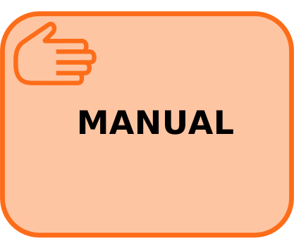
A person performs a Manual Task without a process engine managing the activity. Examples include organizing documents or resolving an invoice issue by phone.
User Task

A process engine assigns a User Task to a person, who completes it and records the result. Examples include reviewing an invoice, approving a vacation request, or handling a support ticket.
Receive Task

A Receive Task represents waiting for a message as a distinct activity in the process. It is shown with an empty envelope symbol.
Receive Task (Instantiating)

An instantiating Receive Task starts a process when it receives a message. Its symbol includes a small event marker in the upper-left corner.
Send Task

A Send Task represents sending a message as part of a process.
Script Task

A Script Task represents a script that a process engine can execute, written in a language the engine supports.
Service Task

A Service Task represents work performed by a software service, such as calling a web service. The model shows the type of activity; the implementation depends on the system running the process.
Business Rule Task

A Business Rule Task represents an activity that evaluates or applies business rules.
Subprocesses and activity markers
A Subprocess contains a flow of its own. You can expand it to show its steps or collapse it to keep the parent diagram focused. Markers can also show that an activity repeats, runs for multiple items, or handles compensation.


Subprocess
A collapsed Subprocess groups steps under one activity in the parent diagram. Expand it when readers need to see the internal flow.
AdHoc Subprocess
An AdHoc Subprocess represents activities without a fixed sequence. The model indicates that the activities can be performed in a flexible order.
Loop marker
A loop marker shows that an activity repeats until its exit condition is met.
Multi-instance marker
A multi-instance activity repeats for a defined set of items. Vertical lines indicate parallel instances; horizontal lines indicate sequential instances.
Compensation marker
A Compensation activity represents work that reverses or offsets the effects of an earlier activity. Connect it to the diagram with an Association, not a Sequence Flow.
Combined markers
You can combine a Compensation marker with loop or multi-instance markers to show how the activity repeats or applies to multiple items.
Gateways
Gateways control how a process branches or merges. They appear as diamonds. The marker inside the diamond identifies the Gateway type and how it handles the paths.
 Exclusive Gateway
 Inclusive Gateway
 Parallel Gateway
 Event Gateway
Exclusive Gateway
An Exclusive Gateway selects one outgoing path. The diamond may contain an X marker or no marker.
Inclusive Gateway
An Inclusive Gateway can activate one or more outgoing paths, depending on the conditions. A matching Gateway later in the process can synchronize the paths that were activated.
Parallel Gateway
A Parallel Gateway activates all outgoing paths when it splits the flow. When it merges paths, it waits for all incoming branches to complete.
Event Gateway
An Event Gateway routes the process based on which event occurs first, such as receiving a message.
Connecting objects
Connecting objects show how BPMN elements relate. Use the right connector for the relationship you want to represent.
 Sequence Flow
 Message Flow
 Association
Sequence Flow
Sequence Flow shows the order of activities and events within a process. It appears as a solid line with an arrowhead and can represent a conditional or default path.
Message Flow
Message Flow shows communication between separate participants, usually represented by different pools. It appears as a dashed line with a circle at the start and an open arrowhead at the end. Do not use it to connect activities within the same pool.
Association
An Association connects an activity or event to an artifact, such as a Data Object or Text Annotation. It adds context without changing the process flow.
Pools and swimlanes
Pools represent participants in a process, such as organizations, departments, or systems. Lanes divide a pool to show responsibilities within that participant.

Use separate pools when you need to show distinct participants and their exchanges. Use lanes to clarify which role or system handles each activity. For more detail, see the documentation on pools and swimlanes.
Collapsed Pool

A collapsed Pool shows a participant without displaying its internal activities. This is useful when the diagram needs to show that an external organization or system is involved, but its internal process is outside the model’s scope.
Artifacts
Artifacts add information and context to a BPMN diagram without changing its Sequence Flow. The main types include Data Objects, Data Stores, Groups, and Text Annotations.
Data Objects and Data Stores
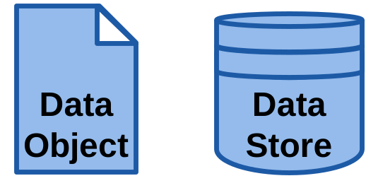
A Data Object represents information used or produced by an activity. Data Input and Data Output show information entering or leaving a process. A Data Store represents information that persists beyond the process instance.
Group

A Group visually gathers related elements. It does not change the process flow.
Text Annotation

A Text Annotation adds an explanation or note to a diagram. Use an Association to connect it to the relevant element.
How do you create a BPMN diagram?
Start with the process question you want the diagram to answer. Then build the model from the main flow outward:
- Set the scope. Choose the process, its start and end points, and the level of detail readers need.
- List the activities. Capture the main steps in plain language before adding symbols.
- Add events and outcomes. Show what starts the process, what can happen along the way, and how each path ends.
- Model decisions. Add Gateways where the flow branches or merges.
- Show participants and responsibilities. Use pools and lanes to make ownership clear.
- Add messages and context. Use Message Flow between participants and artifacts for relevant data or notes.
- Review the model. Walk through each path with people who know the work. Check that the diagram is readable and that the symbols match the intended meaning.
For a guided walkthrough, follow the documentation on constructing a BPMN diagram. You can also open BPMN 2.0 examples in the documentation to see finished models, and copy the patterns that fit your process.
The notation sticks faster when you draw with it. Take a process you already know, describe it in a sentence, and correct the draft the modeler generates; auto-layout arranges the diagram while you look up the symbols above.
BPMN modeling practices that keep diagrams useful
A model is easier to review and maintain when you:
- Agree on the purpose first. A model for discussion may need less detail than one intended for implementation.
- Use standard symbols consistently. Avoid inventing shapes or meanings that other readers will not recognize.
- Name elements clearly. Use terms your process team understands, and make different outcomes easy to distinguish.
- Keep the diagram focused. Use Subprocesses to separate detail from the main flow.
- Show responsibility where it changes. Pools and lanes should clarify participants and ownership, not add empty structure.
- Validate with process participants. Walk through the paths with people who perform or manage the work.
- Review after changes. A diagram describes a process at a point in time. Update it when the process changes.
ProcessMind’s BPMN 2.0 modeler runs in the browser, with AI generation from a description, automatic layouts and model quality checks. Those practices are easier to keep when the tool does part of the work: start with the process you know best, and you have the notation, the review and the first improvement conversation in the same place. For a broader view of how modeling and operational data can work together, read about the combined value of process modeling and process mining.
What changed from BPMN 1.x to BPMN 2.0?
The symbols will look familiar if you are reviewing an older BPMN model. The main differences are in the standard’s precision and portability.
- A shared XML format. BPMN 2.0 defines a format for storing and exchanging models. BPMN 1.x did not define a shared file format, which made it harder to move a model between tools.
- More precise definitions. BPMN 2.0 specifies elements and their relationships in greater detail.
- Support for executable models. BPMN 2.0 is precise enough for a workflow engine to execute a model. Not every process model needs to be executable.
For most new models, BPMN 2.0 is the practical choice because it is the current version supported by modern modeling tools.
What does BPMN 2.0 XML contain?
A BPMN 2.0 XML file stores the model’s elements, connections, names, and diagram layout. It can include the pool and lane structure, Sequence Flow and Message Flow, event and Gateway types, and the positions of elements on the canvas.
XML support makes it possible to exchange models, but it does not guarantee that every tool-specific feature will transfer. A different tool may render the layout differently, and custom fields or review history may not be part of the standard file.
ProcessMind documents how to import and export BPMN files. If you want to compare tools, see our guide to Visio alternatives for BPMN.
BPMN 2.0 poster and symbol reference
Use the poster as a quick reference while you model. The documentation lists the available poster downloads by language.
A poster is what you reach for once you are already drawing, so keep one next to the model you are working on: open the modeler and use the sheet to check a symbol while the diagram is in front of you.
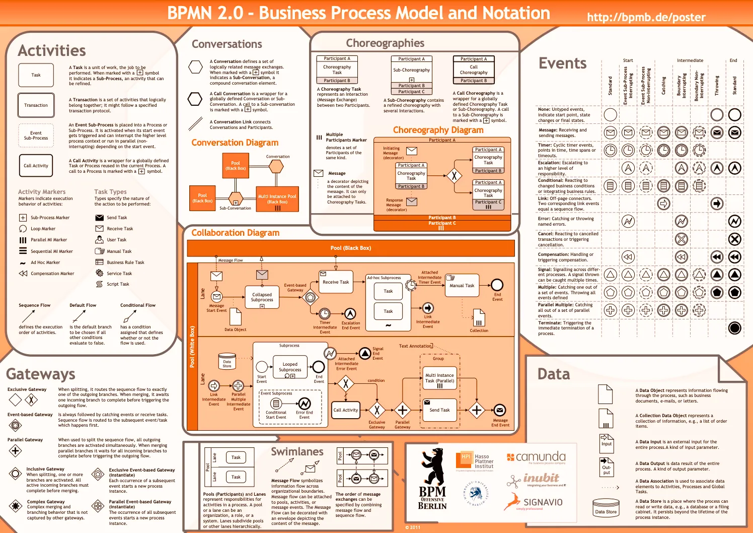
Download the BPMN 2.0 poster in your language
Choose a poster below to open the PDF. The documentation page lists the available versions and remains the reference for downloads.
 English
 Dutch
Dutch German
 French
 Español
 RussianSwedish
 Italian
 Portuguese
 Polish
 Hebrew
 Ukrainian
 Chinese
 Hungarian
 Persian
 English
Acknowledgments
The poster was created in 2010 and translated by researchers and practitioners. We thank the people and institutions who helped make it available.
Original authors: Gero Decker, Jakob Freund, Alexander Lübbe, Jan Mendling, Frank Puhlmann, Torben Schreiter, Matthias Weidlich.
Translations were provided by: Trisotech (French); Ildefonso Montero, Luciano García-Bañuelos, and Marlon Dumas (Spanish); the Business Process Technology Group at Hasso-Plattner-Institute (Russian); Birger Andersson and Petia Wohed (Swedish); Thauris.nl (Dutch); Lucinéia Heloisa Thom and Cirano Iochpe (Portuguese); MGX Infoservice (Polish); Ofir Nimitz and Iftah Peretz (Hebrew); A/Prof Zhang and Lecturer Ms Bai from the School of Software Engineering at Beijing Jiaotong University (Chinese); Istvan Gerecs (Hungarian); and Hamidreza Sarabadani (Persian).
Source: the BPMN 2.0 poster
Where to go from here
You have the symbol reference. Put it to work by creating a model and checking each path with the people who know the process.
Where to Go From Here
You know the notation and you have the reference. The part that sticks is drawing a process you already know, and that can happen today rather than in the next planning cycle.