

BPMN vs UML vs Flowchart: Which Diagram to Use
BPMN vs UML: what each notation models, one table to decide with, and why we standardise on BPMN 2.0 instead of a notation of our own.

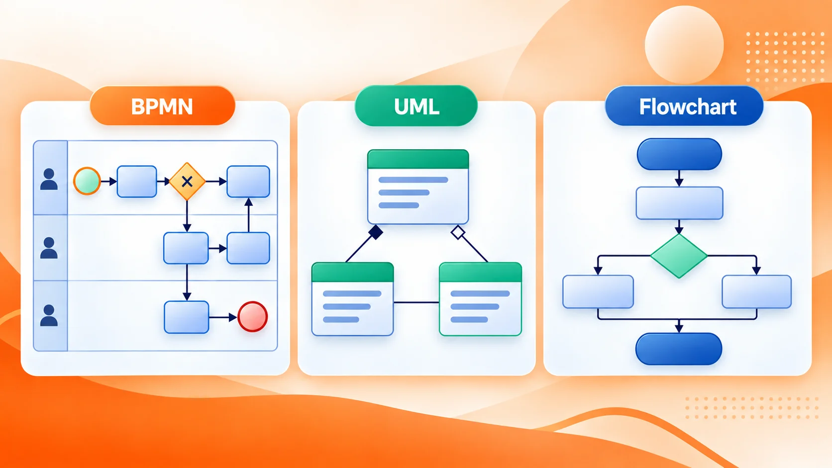
BPMN vs UML comes down to what you need to model. BPMN describes business processes and how work moves between participants. UML describes software structure and behavior. A flowchart is a quick, informal way to show steps and decisions. They can look alike, but they are not interchangeable.
This page compares what each notation is for, gives you one table to decide with, and explains why we model in BPMN 2.0 rather than in a notation of our own.
What does each notation model?
BPMN 2.0 stands for Business Process Model and Notation. It is maintained by the Object Management Group (OMG) and it models business processes: participants, activities, sequence, decisions and the events that trigger or interrupt work. The symbols and the rules for connecting them are defined, so a model can be validated against them, and BPMN 2.0 also defines an XML format for exchanging models between tools. For an introduction to the notation, see what BPMN 2.0 is.
UML stands for Unified Modeling Language, also an OMG standard, for describing software systems and their behavior. It covers class, component, deployment, sequence, activity, state machine and use case diagrams. Activity diagrams are the type that most often overlaps with process modeling.
Flowcharts show steps and decisions with shapes and arrows. There is no governing standard and no fixed rule set, so teams fall back on local conventions: quick to draw, and easy for two people to read differently. The spelling varies too, from flow chart and flow-chart to the common mis-typing flow charter, but it is always the same informal diagram.
BPMN vs UML vs flowchart: how do you choose?
Find the artifact you need to produce, then take the notation in the middle column.
| If you need to model… | Use | Why |
|---|---|---|
| A business process involving people, teams or systems | BPMN 2.0 | Participants, lanes, message flows and events are native to the notation, and the model can be validated and exchanged as BPMN 2.0 XML. |
| Software structure or behavior | UML | It has the diagram types for software: classes, components, deployments, sequences and state machines. Activity diagrams are not a process standard. |
| One procedure, a workshop sketch or a single decision | Flowchart | Nothing to install and no rules to follow, which is also why it does not survive as a maintained model. |
| A process that has to be validated or exchanged between tools | BPMN 2.0 | The notation has rules to check the model against, and a file format to move it. |
| A decision tree, a calculation or a data flow | Neither | Use the notation designed for that artifact; forcing it into a process diagram hides the logic behind familiar-looking boxes. |
The question is not which notation looks familiar. It is what the diagram has to communicate, and who has to use it after you draw it.
How do you run this with a team? Agree on the artifact first, in one sentence, and resist choosing by tool: whatever a vendor or an old licence prefers is not an argument about notation. Where two notations both fit, take the one more readers can interpret without help, and write down the conventions you are adding on top of it, such as naming, layout and level of detail, so the next model does not invent its own. A good test is to hand the diagram to someone who was not in the workshop and ask what happens next. If they cannot answer, the notation is usually not the problem.
Why do BPMN and UML look similar?
A UML activity diagram and a BPMN process diagram can both use rounded rectangles for activities, diamonds for decisions and bars for parallel paths. At a glance they may look much the same.
The meaning behind the shapes is different. A UML activity diagram describes behavior in a software or system context. A BPMN diagram describes work performed by participants, which may include people, departments and systems. BPMN has specific elements for participants, lanes, message flows and events, and UML activity diagrams do not provide those business process concepts in the same way.
Process intelligence tools tend to use their own notations. We decided to use BPMN 2.0 because it is the only real standard. Is it perfect? No. But it is what everybody ended up using, and a model that outlives the tool that drew it is worth more than a prettier diagram nobody else can read.
Can you mix BPMN, UML and flowcharts?
Yes, as long as each diagram says which notation it uses:
- Document the business process in BPMN and the software that supports it in UML. Keep the link explicit, for example with a shared name or identifier.
- Use UML for software design even when a BPMN process surrounds it. Each model answers a different question.
The problem is not using several notations across an organisation; we do it ourselves. It is mixing them inside one diagram without saying so: if a reader cannot tell whether a shape is an activity, a software element or an informal step, the diagram cannot be trusted.
When is a flowchart the better choice?
BPMN vs flowchart is the same question at a smaller scale, and the answer is usually about maintenance. A flowchart is the better choice for a short procedure, a workshop sketch or a one-off explanation: a few steps and a decision, with no structure the team does not need yet.
Choose BPMN as soon as the diagram has to be read consistently, checked against notation rules, reviewed again next quarter or shared across teams. If you are unsure, sketch it first and formalise it in BPMN when the process earns a model. For a wider view of diagram types, see what process mapping is, and if you are moving off an older diagramming tool, read Visio alternatives for BPMN.
What about the flowcharts your team already has? Treat them as input rather than as the model. A workshop sketch is often the fastest way to agree on scope, and redrawing it in BPMN takes an hour or two once the process matters, which makes the flowchart a draft rather than a rival. What we avoid is maintaining the same process twice, in two notations: then neither version is authoritative, and the question of which one is current becomes the point of the meeting.
How do you keep a BPMN model portable?
Draw it somewhere the notation stays standard and the file can leave. ProcessMind models BPMN 2.0 in the browser and imports and exports BPMN files, so the diagram is not trapped in the product that drew it. You can also keep the model beside the mined process, which is how the process you intended gets compared with the one your systems recorded.
See how the ProcessMind modeling workspace works, or review the supported BPMN elements.
Where to Go From Here
You have picked the notation that fits the artifact, and the next question is whether the tool keeps it standard, validatable and exportable.